

The TBM Hard rock shield was designed by Mitsubishi Japan Company and constructed by NEYRPIC FRAMATOME MECHANIQUE (NFM) FRANCE.
The length of the TBM, including back-up Gantries and California switch is 150m long. The overall weight is 1650 tones.
The TBM works comprise of 850.000 m3 excavated material & 350.000 m3 of Concrete. The TBM works with a four-shift system, 35 men per shift surface and underground activities for seven days per week. The TBM crew was 21 men. The TBM 1 named “IASON” and the TBM 2 “PERSEFONI”.
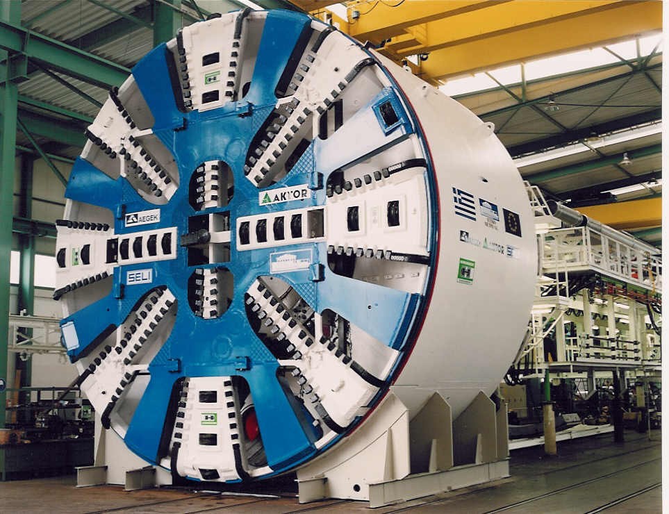
The TBM can be separated into two sections:
- The TBM Cutter head (Shield).
- The Back – up Gantries. The first excavation by the TBM1 started on 25 April 1994 from Larissa station. The first Breakthrough at Deligianni Station was on 13, May 1995.
The rates of the TBM have been 4.5 to 17 m / working day or about 3 to 12 rings/working day. Individual daily rates, not considering stoppages for breakdown, etc. ranged from 19.5 to 24 m / working day or about 13 to 16 rings / working day. A typical cycle for 1,5m advance of TBM requires 25 min. for excavation, 30 min. for ring erection and 5 min. for cleaning and preparation. The TBM cutter head, the revolving part, excavates (9516mm diameter) the hard and soft ground Tunnel with a variable rotational speed of the cutter head from 0 to 4 rpm and rated torque 1140 to 1368 tons – m. The length of the Cutter Head is 1500 mm long. The cutter head has 63 pieces hard disks, 17” inch diameter placed at individual radius & 200 pieces drag bits.
The disc cutters and drag bits could be replaced from the rear side of the cutter head. The two over cutters mounted at the periphery of the cutter head created an over cut of 60mm and allowing a better steering of the shield and reducing the TBM friction forces.
The cutter head rotate in both directions, clockwise and anti clockwise by 16 hydraulic motors (180kw) reducing gears with maximum output speed 57,6 rpm and maximum working pressure 350 bars. The propulsion of the TBM is electric hydraulic.
The front shield has an outside diameter 9456 mm and the rear shield an outside diameter 9440 mm. The overall length of front and rear shield is 7515 mm long. The shield weights 880 tones. The skin of the rear shield is 92 mm thick.
The front and rear shields are articulated one to the other. The two parts of the shields are connected by 16 articulation jacks 360 mm diameter, 260 bar which make it possible to orient one body in relation to the other in all spatial directions.
The total stroke of the articulation cylinders is 500 mm and allow for retraction of the front shield plus cutter head up to 300 mm thus creating access to the face. Minimum tunnel curve radius of the profile is 300m & compensation curve radius is 250m.
The amount of the excavated material for a complete stroke of 1,5m advance was approximately 192m3. The excavated material passes into the cutter head chamber through openings (32 % of the cuter head face is open to the ground) of the cutter head periphery.
Then picked up by the cutter head blades and lifted up the top part, it falls into the hopper. The cutter head hopper empties the excavated muck onto a conveyor belt (primary conveyor) located at the level of the tunnel axis.
The length of the primary conveyor is 18,25 m and 1,2 m width. From the primary conveyor, the muck is dropped onto the secondary belt conveyor 28,80 m length and then to the third conveyor belt 38,00 m length located on the structures of the back-up gantries.
The third conveyor then pours into a shuttle conveyor 30 m length that moves parallel to the tunnel axis for filling the mucking cars without moving them.
At TBM operation all the excavated material is collected to the muck skips by the belt conveyors. The conveyor belts are designed for a capacity of 950 t/h or 750 m3/h.
If water appears in the ground, the primary conveyor belt is retracted and a safety gate isolates the cutter head chamber from the interior area of the shield. An emergency pump 140 kW is installed in front of the hopper to evacuate the water from the cutter chamber via tube extension device.
The flow rate is 82 lt./s and 60 m of water pressure. The max inflow of ground water encountered during excavation was 120 lt. / min.
The TBM moves forward by pushing against the last prefabricated segmental tunnel concrete ring with the 28 hydraulic thrust jacks (320 mm diameter) and with 5600 tones (260 bar each Jack) force.
The resultant force on the ground face was up to 3000 tones or 42 tones/m2. The maximum extended stroke of the pushing jacks is 2300 mm allowing sufficient space for ring erection, within the rear shield.
The front shield of the TBM is fitted with 6 radial jacks (front grippers) with conical shape (250mm diameter, 350 bar) and extended stroke up to 150 mm. The front grippers are preventing the TBM from rolling during excavation on hard rock ground conditions.
The conical shape is preventing damage of the grippers steel during excavation.
The rear shield has 4 grippers (160mm diameter, 350 bar) with an extended stroke of 150mm.
The rear grippers keep the rear shield in position when the front shield is retracted with the articulation jack for changing the cutter discs and for ground inspection.
A neoprene tail seal 270mm long, mounted on the edge of the rear shield, provides leak tightness between the ground and shield during TBM advance and grouting the annulus void between the ring and the excavated tunnel.
For inspection of the neoprene the tail seal, the extension of the front grippers and retraction of the rear shield is required.
The TBM control room placed at back up 1st gantry is about 25m backwards from the excavated face. The operator controls the front and rear shield to keep them on line and level.
The acceptable tolerance of the segmental tunnel lining from the Design Tunnel Axis (DTA) is 80mm.
The TBM front and rear shield position is accurately defined by the guidance system, which records its attitude in terms of lead, look-up or overhang and roll.
The TBM is guided by a system of laser sighting (CAP/ZED).
The ZED system uses laser indicates the Horizontal and Vertical position of a tunnel-boring machine and transmits this to cap system.
The laser beam is set up and aligned by conventional Theodolite techniques. The laser beam provides a clearly identifiable line and a recognizable spot continuously projected on the rear shield target face by using survey station in the crown of the tunnel.
The Cap system read those values and the pilot, in manual or automatic mode, tries to maintain those values by activating the pressures and the flow rate of the pushing jacks, the speed of rotation and the Cutter Head torque.
In case of important deviation noted by the ZED system a compensation curve is defined which consists to progressively bring the Tunnel boring machine on the theoretical path by several cycles of boring strokes.
